How can we help you?
Recent Searches Clear All
News
For the inspection, repair, operation, and digital management of urban water supply and drainage networks
Sep.25,2026
Pipe Inspection Equipment Applications in Industrial Pipeline Inspection cover the detection, measurement, and documentation of corrosion, cracks, wall-thickness loss, deformation, leaks, blockages, and insulation-related defects. The main categories include visual cameras, robotic crawlers, smart pigs, ultrasonic testing systems, electromagnetic inspection tools, sonar, and leak-detection equipment. Each technology addresses different pipe materials, diameters, access conditions, and defect types.
Industrial pipeline inspection cannot depend on visual checks alone. A camera may show a crack or deposit, but it cannot always measure remaining wall thickness or identify a defect beneath insulation. I use a risk-based combination of inspection technologies to connect visible evidence with measurable data, maintenance priorities, and repair decisions.
!
Pipe Inspection Equipment refers to the instruments, robotic systems, sensors, cameras, and software used to examine the internal or external condition of pipelines without dismantling the entire asset. The equipment may record video, measure wall thickness, detect metal loss, locate leaks, identify deformation, or map internal obstructions. In practice, the equipment is one part of a wider inspection service that also includes preparation, data interpretation, defect verification, and reporting.
The correct selection depends on the pipeline threat rather than on the equipment category alone. A wastewater line with sediment and standing water may require a crawler and sonar, while a pressurized oil pipeline may require in-line inspection tools. A process pipe under insulation may need electromagnetic or ultrasonic testing because direct visual access is limited.
Visual inspection remains useful because it provides direct evidence of coating damage, corrosion products, weld irregularities, deposits, open cracks, and foreign objects. However, visual systems are affected by lighting, water turbidity, camera angle, surface contamination, and access restrictions. A visually clean surface can still have internal wall loss or a defect hidden beneath insulation.
Non-destructive testing for industrial pipelines adds measurement and material-response data. Ultrasonic testing can estimate wall thickness, magnetic methods can indicate ferromagnetic metal loss, and electromagnetic testing can identify changes in conductivity or permeability. Leak detection equipment can also reveal a failure mechanism before a visible leak develops.
I treat visual inspection as an observation layer, not a complete condition assessment. The most reliable workflow combines camera evidence with a method that matches the suspected threat, followed by targeted verification when the initial result could affect a repair or shutdown decision.
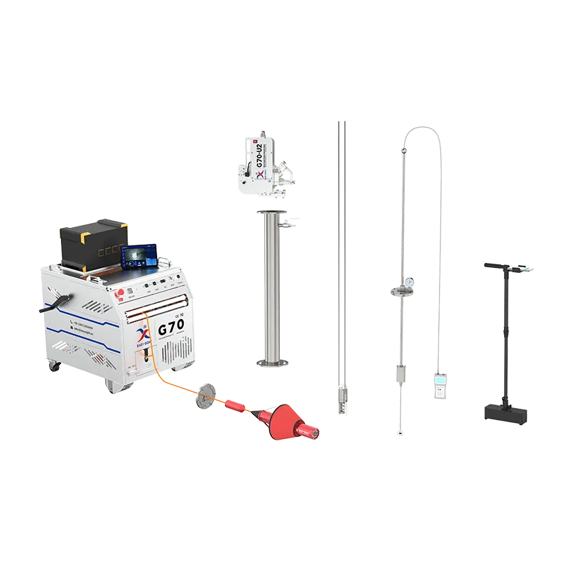
Remote visual inspection equipment for pipelines includes push cameras, pole cameras, manhole cameras, pan-and-tilt systems, and crawler-mounted CCTV. These systems document internal conditions without requiring personnel to enter confined spaces. Typical findings include root intrusion, cracking, corrosion deposits, joint displacement, deformation, blockage, sediment, liner damage, and standing water.
Camera systems are usually the first inspection layer because they are comparatively simple to deploy and produce an understandable visual record. They are especially useful for water and wastewater pipelines, utility conduits, process drains, and large-diameter pipes with accessible entry points. Their limitation is that video alone generally does not provide dependable quantitative data for wall thickness, subsurface flaws, or defects hidden behind deposits.
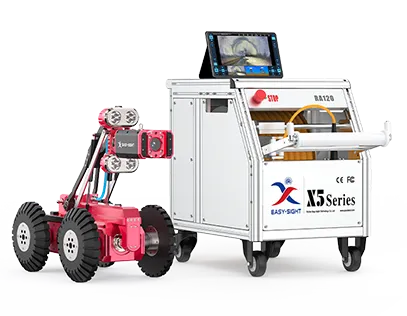
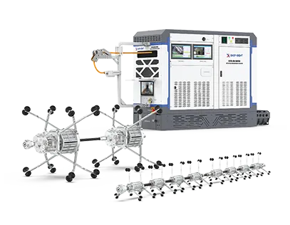
Easy-Sight provides several pipe inspection system categories, including crawlers, pole cameras, manhole cameras, sonar systems, long-distance detection systems, small-diameter systems, high-precision systems, and all-terrain inspection platforms. Its published equipment range includes systems for pipe diameters from small community pipelines to large industrial and municipal assets.
Robotic crawlers carry cameras, lights, sensors, and sometimes measurement devices through a pipeline. They are suitable when a pipe is too long, hazardous, deep, or inaccessible for manual inspection. Wheels, tracks, articulated bodies, and all-terrain designs help the robot pass over uneven surfaces, minor obstacles, and changes in elevation.
Crawler selection should include pipe diameter, internal flow, cable length, travel distance, turning radius, obstacle height, and the required recording resolution. For example, Easy-Sight lists the X5-HT5 pipe inspection robot for DN200–1200 mm pipelines, with a stated maximum travel speed of 41 m/min and detection distance of up to 500 m. These figures are useful for planning, but actual operating speed will depend on water, debris, bends, slope, and image quality requirements.
Crawler systems are effective for locating defects and creating a visual condition register. They are less suitable when the pipeline is fully pressurized, contains aggressive flow, has severe blockage, or requires volumetric measurement through thick coatings. In those cases, I would combine crawler data with ultrasonic, electromagnetic, sonar, or pressure-based methods.
Smart pigs are in-line inspection tools that travel inside a pipeline with the product flow or a controlled propulsion system. Depending on the sensor package, they can detect corrosion, metal loss, cracks, dents, ovality, bending strain, and some forms of weld-related damage. Magnetic flux leakage, ultrasonic inspection, and electromagnetic acoustic technologies are common approaches in this category.
Smart pigs require suitable launch and receiving facilities, compatible pipe geometry, controlled operating conditions, and a pipeline that can pass the tool. Valves, tees, diameter changes, bends, deposits, and restrictions can affect tool passage. The inspection plan must therefore confirm internal diameter, bend radius, pressure, flow, product compatibility, and safe retrieval arrangements before deployment.
In-line inspection produces valuable data for pipeline integrity management tools because defects can be referenced to distance, clock position, and pipeline features. However, indications still require engineering assessment and may need confirmation through direct measurement, excavation, or another non-destructive testing method.
Ultrasonic testing equipment for pipe inspection sends high-frequency sound waves into the pipe wall and analyzes reflected signals. Thickness gauges are used to measure remaining wall thickness, while more advanced systems can support weld inspection, crack detection, corrosion mapping, and phased-array imaging. The method is useful for carbon steel, stainless steel, pressure vessels, process piping, and accessible external surfaces.
Ultrasonic results depend on calibration, probe selection, surface condition, couplant, temperature, material structure, and operator technique. Rough scale, coatings, pitting, curved surfaces, and inaccessible areas can reduce measurement reliability. I require calibration blocks or reference standards appropriate to the material and thickness range before collecting readings.
UT is particularly valuable after a camera identifies corrosion or after a risk model identifies a high-consequence location. It can quantify wall loss and support remaining-strength calculations, but it does not automatically explain the cause of corrosion or confirm the full length of a defect. A grid-based thickness survey or encoded scan may be necessary when isolated spot readings are insufficient.
Magnetic flux leakage inspection for pipelines magnetizes a ferromagnetic pipe and detects changes in the magnetic field caused by metal loss. Corrosion pits, general wall thinning, and localized defects can create detectable leakage patterns. The technology is widely associated with in-line inspection, but related magnetic testing methods can also be applied to accessible external surfaces.
Magnetic inspection is not a universal solution. It is primarily suited to ferromagnetic materials and may have reduced sensitivity to certain crack orientations, shallow defects, complex geometries, heavy coatings, or defects near welds. Indications also require sizing and interpretation because signal strength is affected by defect shape, depth, width, tool speed, magnetization level, and sensor lift-off.
I use magnetic results as an indication and prioritization tool rather than treating every signal as a confirmed failure. Where the consequence of an incorrect decision is high, I recommend secondary verification with ultrasonic thickness measurement, magnetic particle testing, radiography, or direct examination.
Leak detection equipment identifies pressure loss, acoustic emissions, flow anomalies, or other signals associated with leakage. Some systems are designed for water supply pipelines, while others address industrial process lines or buried infrastructure. Easy-Sight lists a water supply inspection robot with a stated minimum detectable leakage point of 0.04 L/min, leak-location accuracy of ±0.5 m, detection depth of 5 m, and inspection distance of 600 m.
Sonar systems are useful in submerged or water-filled pipelines where cameras cannot obtain a complete view. They can estimate internal geometry, sediment levels, voids, and blockage profiles. Sonar does not replace visual inspection because it cannot provide the same surface detail, but it can extend coverage through turbid water.
Specialized tools also include diameter gauges, panoramic manhole systems, insulation inspection instruments, and high-temperature or hazardous-area equipment. For insulated pipelines, I consider external corrosion under insulation, moisture ingress, damaged cladding, and thermal restrictions before deciding whether to remove insulation or use a screening method.
The main pipe inspection equipment applications are determined by the active threat, the operating environment, and the consequence of failure. The table below connects typical threats with suitable inspection methods and important limitations.
| Pipeline threat or condition | Suitable equipment | Primary output | Main limitation |
|---|---|---|---|
| Internal corrosion and deposits | CCTV crawler, UT, MFL | Visual evidence, wall thickness, metal-loss indication | Deposits can hide defects |
| Cracks and weld flaws | UT, phased-array UT, electromagnetic testing, visual camera | Crack or flaw indication | Orientation and surface condition affect detection |
| Wall-thickness loss | UT, MFL, ultrasonic smart pig | Thickness readings or metal-loss sizing | Requires calibration and engineering interpretation |
| Deformation and ovality | CCTV, laser profiling, geometry pig | Shape, diameter, and obstruction data | Access and tool passage may be restricted |
| Leaks | Acoustic, pressure, flow, sonar, specialized robot | Leak location or abnormal flow evidence | Noise and operating changes can create false indications |
| Blockages and sediment | CCTV, sonar, crawler | Obstruction type and approximate extent | Heavy blockage may prevent equipment passage |
| Corrosion under insulation | Visual external inspection, UT, electromagnetic screening | Coating, moisture, and wall-loss evidence | Insulation may limit direct access |
| Long-distance internal assessment | Smart pig or long-cable crawler | Distance-referenced defect data | Requires suitable geometry and operating controls |
In oil and gas pipelines, the focus is often corrosion, cracking, dents, seam defects, and leak prevention. In chemical facilities and process plants, inspection planning must also account for aggressive fluids, temperature, pressure cycling, and complex pipe routing. In water and wastewater systems, the common concerns are leakage, infiltration, root intrusion, sediment, joint displacement, corrosion, and structural deformation.
Power-generation facilities require inspection around boiler feedwater, cooling-water, condensate, steam, and chemical dosing systems. Utilities may need compact crawlers, pole cameras, or leak-detection systems for aging networks with limited shutdown options. Small industrial businesses can begin with a targeted visual and thickness program, then add specialized inspection methods at locations where the initial data indicates elevated risk.
I begin by identifying the pipe material, diameter, length, wall thickness, pressure, temperature, contents, coating, insulation, flow condition, access points, and known failure history. I then classify the likely threats, such as internal corrosion, external corrosion, cracking, erosion, blockage, deformation, or leakage. This prevents equipment selection based only on brand, camera resolution, or purchase price.
The inspection plan should also record whether the pipe is live, isolated, drained, cleaned, purged, or suitable for personnel access. Hazardous-area requirements, confined-space controls, electrical classification, decontamination, and retrieval planning can determine which equipment is acceptable before technical performance is considered.
Preparation may include cleaning, flushing, isolation, temporary access, flow control, lighting checks, battery charging, cable inspection, and communication testing. For ultrasonic work, I confirm surface preparation, calibration blocks, probe condition, couplant compatibility, and temperature limits. For robotic systems, I verify traction, camera focus, lighting, cable length, wheel or track condition, and recovery procedures.
I also establish inspection acceptance criteria before deployment. These criteria may include minimum wall thickness, allowable deformation, reportable crack dimensions, maximum obstruction size, location accuracy, image quality, and required data formats.
During the inspection, I record pipe distance, clock position, defect type, dimensions, operating conditions, and image or sensor evidence. A second operator or reviewer should check significant indications, especially when lighting, water, deposits, or motion blur could affect interpretation. Equipment readings must be compared with calibration checks taken before and after the survey.
False positives can result from weld geometry, scale, sensor lift-off, magnetic noise, reflections, cable movement, or camera perspective. False negatives may occur when a defect is hidden by sediment, outside the sensor’s range, aligned poorly with the inspection method, or located beyond the accessible section. Data validation is therefore a separate activity, not an assumption.
When an indication could trigger a shutdown, excavation, replacement, or pressure restriction, I use a secondary method. A camera indication of corrosion may require UT thickness mapping, while an MFL signal may require direct ultrasonic sizing. A suspected leak may need pressure testing, acoustic confirmation, flow analysis, or a controlled excavation.
Secondary inspection should be based on risk and uncertainty. Minor, isolated indications in a low-consequence line may receive a scheduled follow-up, while a deep metal-loss indication near a weld, support, valve, or high-consequence area may require immediate verification.
The final report should connect every finding to a location, evidence type, measurement, confidence level, recommended action, and review date. Pipeline integrity management tools can combine inspection history with corrosion rates, design limits, operating data, repair records, and consequence assessments. This creates a basis for ranking repairs rather than treating every defect equally.
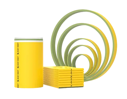
Repair planning may involve coating replacement, clamp installation, localized excavation, spool replacement, liner rehabilitation, pressure reduction, cleaning, or additional monitoring. Easy-Sight’s product range also includes inspection and pipe rehabilitation systems, which illustrates the practical connection between defect detection and corrective work, particularly in water and drainage networks.
I use the following decision matrix when comparing equipment categories, inspection services, and supplier-specific products:
| If the priority is… | Start with… | Confirm before purchase or mobilization |
|---|---|---|
| Fast internal visual assessment | CCTV crawler or push camera | Diameter range, cable length, lighting, image storage |
| Quantified wall-loss measurement | UT thickness system | Calibration process, probe range, surface preparation |
| Long-distance pressurized pipeline data | Smart pig or in-line inspection service | Launchers, receivers, bends, valves, product compatibility |
| Corrosion screening in ferromagnetic pipe | MFL inspection | Material suitability, coating effects, sizing accuracy |
| Water-filled or turbid pipe inspection | Sonar with camera support | Water depth, sediment profile, sonar resolution |
| Leak location | Acoustic, pressure, flow, or robotic leak system | Background noise, flow stability, location accuracy |
| Deformation and blockage assessment | Crawler, laser profile, or geometry tool | Obstacle clearance, turning radius, access conditions |
| Corrosion under insulation | External UT or electromagnetic screening | Insulation access, temperature, coating condition |
The commercial comparison should include more than equipment price. I calculate total inspection effort from mobilization, shutdown impact, cleaning, access preparation, operator skill, calibration, data review, reporting, transport, maintenance, and repeat inspection requirements. A lower purchase price can produce a higher total cost if the system cannot pass the pipe, requires extensive manual interpretation, or produces data that must be collected again.
I also distinguish between a product, an inspection service, and a complete supplier solution. A product is the physical instrument or robot; a service includes personnel, deployment, interpretation, and reporting; a complete solution may add data management, rehabilitation, and follow-up planning. Easy-Sight, founded in 2010 as Wuhan Zhongyi IoT Technology Co., Ltd., presents inspection, rehabilitation, operation, and digital management as connected areas, with published deployment figures including more than 4,000 pipeline inspection robots and service coverage across more than 50 nations.
Pipe Inspection Equipment Applications in Industrial Pipeline Inspection are most effective when each technology is matched to a defined threat, operating condition, and decision requirement. Visual cameras and crawlers provide direct evidence of internal condition, ultrasonic systems quantify wall thickness, magnetic flux leakage identifies metal-loss indications, smart pigs cover suitable long-distance pipelines, and sonar or leak-detection systems address submerged or inaccessible conditions.
I recommend beginning with a documented threat assessment, then selecting the smallest combination of methods that can produce reliable evidence for the maintenance decision. Before deployment, confirm access, pipe geometry, calibration, safety controls, reporting requirements, and shutdown impact. After inspection, validate important indications with a secondary method and transfer the results into pipeline integrity management tools.
For operators comparing industrial pipeline inspection equipment, the right choice is not simply the system with the most sensors. It is the equipment or service that can inspect the required section, detect the relevant defect type, produce traceable measurements, and support a repair decision at a reasonable total inspection effort.
Latest News
Sep.25,2026
Pipe Inspection Equipment Applications in Industrial Pipeline Inspection
Sep.24,2026
How to Maintain Pipe Inspection Equipment for Long-Term Reliable Performance
Sep.23,2026
Portable vs Robotic Pipe Inspection Equipment: Which Solution Fits Your Project?
Get Friendly Advice, Tailored to You!
Let's Talk About Your Project